Shipboard network cables are specifically designed to cope with the complex and harsh marine environment. In terms of design and manufacturing, they need to meet stringent performance standards. To this end, the International Electrotechnical Commission (IEC) has set forth numerous standard specifications for shipboard network cables. Among them, standards such as IEC 60287 (conductor resistance), IEC 60092 (insulating materials), and ISO/IEC 11801 (impedance) have put forward detailed requirements for electrical characteristics.
In order to ensure that shipboard network cables can provide stable, fast, and reliable network connections in extreme marine environments, it is necessary to guarantee that their electrical characteristics comply with international standard specifications and various design standards.
The following will introduce several important electrical characteristics of shipboard network cables and their related requirements.
1.Conductor resistance
In shipboard network cables, the magnitude of conductor resistance mainly depends on the conductor material, cross-sectional area, cable length, and ambient temperature. When current flows through the cable, the resistance of the shipboard network cable is directly proportional to the voltage drop, and its change can affect the transmission efficiency and stability. If the conductor resistance is too high, it will reduce the stability of transmission.
The testing process of conductor resistance is as follows:
Select the network cable to be tested and cut a segment of a specified length for subsequent calculations; before testing, strip the insulation layer at both ends of the network cable to expose clean and undamaged conductors; control the ambient temperature (usually 20℃) and humidity within the standard range, and use a high-precision digital multimeter to measure the conductor resistance; after ensuring the multimeter is accurately calibrated, set it to the appropriate resistance measurement range. For thinner network cables, a low resistance range may be needed; connect the test leads to both ends of the conductor of the network cable, ensuring good contact, record the measurement result, and calculate the resistance value per unit length based on the cut length and cross-sectional area of the conductor. Take multiple measurements and calculate the average value to improve accuracy.
Through this test, the test results should be compared with the design values (for example, the conductor resistance of Category 5e network cables should not exceed 93.8Ω/km) to ensure that the resistance value meets the design standards and does not affect the efficient transmission of data even under extreme conditions.
2.Characteristic impedance
Characteristic impedance is a key electrical parameter of shipboard network cables, affecting the transmission efficiency and integrity of signals. Characteristic impedance is a frequency-dependent quantity, and in high-frequency or broadband applications, it is approximately constant. It is related to the structure of the network cable, such as the stranding method and insulating materials.
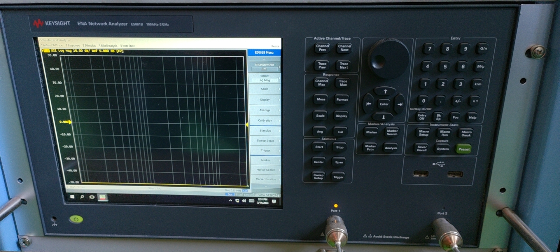
Testing of characteristic impedance:
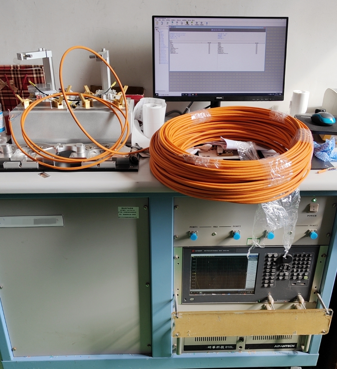
A vector network analyzer (VNA) is typically used to measure characteristic impedance. The VNA is used to measure the reflection coefficient, and the characteristic impedance is calculated from the reflection coefficient. Before measurement, the instrument must be calibrated, and environmental factors should be excluded, such as controlling temperature. The frequency range of the VNA’s test usually needs to cover the expected frequency range of the network cable, such as 1MHz to 1000MHz. The specific range depends on the design of the network cable.
Generally, the characteristic impedance of shipboard network cables should be maintained at 100Ω (at 100MHz) to ensure lossless signal transmission.
3.Insulation resistance
The insulation resistance of shipboard network cables is an important indicator of their insulation performance. Since they have to cope with various harsh marine environments, such as immersion in high-salinity seawater, mechanical vibrations caused by navigation, and temperature fluctuations, the requirements for the insulation resistance of shipboard network cables are much higher than those of general indoor network cables. This is to prevent current leakage and ensure safety. In fact, this is a requirement for the insulating layer, and good insulating materials, such as low-smoke zero-halogen (LSZH) materials, should be used.
Measurement of insulation resistance:
A megohmmeter is generally used to measure insulation resistance. A higher test voltage (500V/1000V) can be applied to more accurately measure the leakage current. Before testing, the test points of the network cable should be cleaned to remove dirt and oxidation layers, reducing errors. During the measurement, the red test lead (L) of the megohmmeter is connected to the conductor of the network cable, and the black test lead (E) is connected to the shielding layer or ground wire of the network cable. Slowly rotate the handle of the megohmmeter to the specified speed (usually 120r/min), and read the resistance value after it stabilizes. After the test, a discharge process should be carried out to prevent electric shock or damage to electronic equipment.
To ensure the electrical safety and long-term reliability of the operation of shipboard network cables and prevent short circuits, the measured value of insulation resistance must meet the industry standards or the specifications of the manufacturer. Under special requirements, the insulation resistance value may need to reach a specific megaohm level.
4.Attenuation characteristics
Attenuation refers to the energy loss during the signal transmission process. It is often necessary to design with the goal of minimizing attenuation to ensure the strength and clarity of signals transmitted over long distances through shipboard network cables. Since copper has a low resistivity (approximately 1.724×10^-8 Ω·m), it helps reduce energy loss and signal attenuation during transmission, which is why copper conductors are commonly used in network cables.
Attenuation testing:
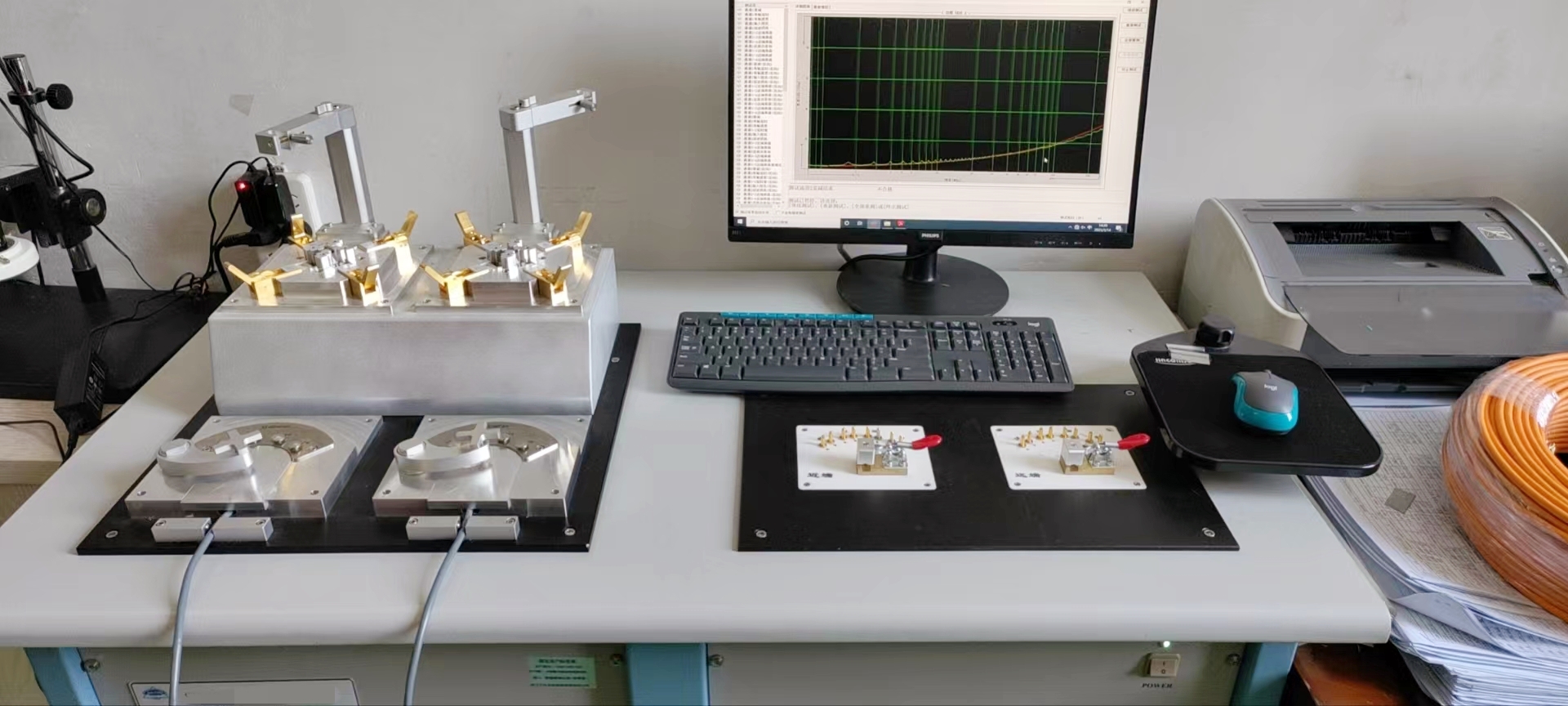
Professional network testers, such as the Fluke DTX-1800 or more advanced testing equipment, should be used. These devices can accurately measure the attenuation of the link. During the testing process, the instrument sends a series of signals at different frequencies and measures the attenuation of the signals when they reach the other end.
Industry standards should be followed to ensure that the testing conditions and results meet the specifications.
Although the test results can show the signal integrity of long-distance transmission through shipboard network cables, it is still recommended in practical applications to keep the single segment length within 100m to avoid long-distance transmission and ensure that the network cables perform at their best.
5.Skew
The skew of shipboard network cables refers to the time difference in which signals from the four pairs of twisted wires travel from the transmitting end to the receiving end. This difference is caused by variations in the physical length, material, or stranding density of each pair within the cable. Ideally, signals from all pairs should arrive simultaneously. This parameter is particularly important for high-speed networks, such as Gigabit/Ethernet.
Skew testing:
Professional network testers that support skew measurement, such as the DSX series from Fluke Networks, should be used for this determination. Before testing, confirm the length and type of the network cable installation to ensure it complies with design specifications. Connect the tester to both ends of the network cable and, once stable, begin the test. The tester will send signals and measure the transmission time for each pair, displaying the skew value for each pair as well as the overall skew.
According to industry standards (such as ISO/IEC 11801) and relevant marine cable specifications, the maximum skew is typically limited to 50ns/100m. For shipboard network cables, the maximum skew between any two pairs for CAT5E, CAT6, and CAT6A cables should not exceed 45ns/100m, and for CAT7 and CAT7A cables, it should not exceed 25ns/100m.
Skew is also a crucial electrical characteristic that requires adequate attention during the design, installation, and maintenance processes to ensure the efficiency and reliability of marine communication systems.