In the previous article, we discussed the structure of marine optical cables. This article will focus on the working principles of marine optical cables.
As a critical medium for information transmission, marine optical cables play a vital role in the shipping and offshore industries. They facilitate the transmission of large amounts of information both within the vessel and between the vessel and the outside world. This information is directly related to navigation safety, operational efficiency, and the quality of life for the crew.
So, how do marine optical cables achieve information transmission? Let’s explore the working principles of marine optical cables.
1. Principle of Optical Fiber Transmission
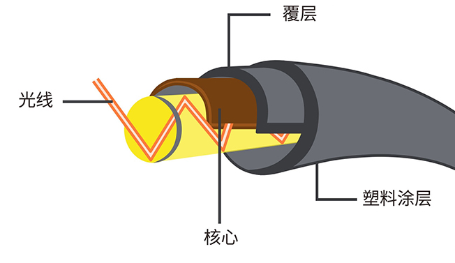
Marine optical cables transmit optical signals through internal optical fibers, based on the principle of total internal reflection. When an optical signal enters the interface between the core and the cladding at an angle greater than the critical angle, total internal reflection occurs due to the slightly higher refractive index of the core compared to the cladding. The light then propagates in a “W” shaped trajectory within the core. This method allows optical fibers to transmit optical signals over long distances with minimal loss, typically only 0.2-0.5 dB/km, which is significantly lower than traditional cables.
2. Working Principle of Marine Optical Cables
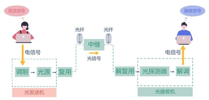
Marine optical cables can only transmit optical signals, while information is usually transmitted, exchanged, stored, and retrieved in the form of electrical signals. Through the conversion between optical and electrical signals and the interconnection of optical cables with various devices, efficient information transmission can be achieved both within the vessel and between the vessel and the outside world. The transmitting end converts electrical signals into optical signals through optical signal modulation; the optical cable serves as the transmission medium, ensuring efficient transmission of optical signals; and the receiving end converts the optical signals back into electrical signals through optical signal demodulation.
2.1 Optical Signal Modulation
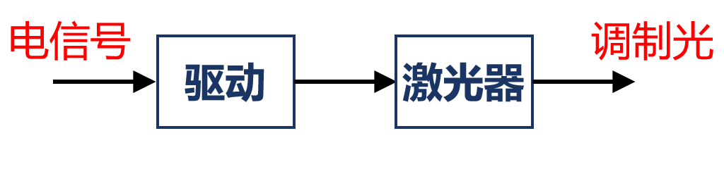
In fiber optic communication systems, electrical signals carrying various forms of information (such as voice, data, and images) must first be converted into optical signals before being transmitted through the optical fiber. Optical signal modulation uses characteristics such as light intensity, phase, frequency, and polarization to convert electrical signals into optical signals. Common modulation methods include intensity modulation, phase modulation, frequency modulation, and polarization modulation.
2.1.1 Intensity Modulation
Intensity modulation is one of the most commonly used methods for optical signal modulation. It represents different information by varying the intensity of the light. For example, in digital communication, the presence or absence of light can represent binary “1″ or “0,” while in analog communication, continuous changes in light intensity can transmit the amplitude of the analog signal. Intensity modulation is cost-effective and suitable for various types of light sources and modulators. Common light sources for intensity modulation include semiconductor lasers (LD) and light-emitting diodes (LED). Semiconductor lasers offer high light intensity and good monochromaticity, producing high-power, narrow-linewidth optical signals suitable for long-distance, high-speed optical communication systems. LEDs, on the other hand, have lower power consumption and longer lifespans, making them suitable for short-distance, low-speed optical communication applications.
2.1.2 Phase Modulation
Phase modulation can be divided into absolute phase modulation and relative phase modulation. Absolute phase modulation directly maps information onto the absolute phase of the optical signal, while relative phase modulation represents information by changing the phase difference between adjacent optical signals. The advantage of phase modulation is its lower power requirement for the light source and high resistance to interference, as phase information is less affected by fluctuations in light intensity. Phase modulation is widely used in high-precision measurement and sensing systems.
2.1.3 Frequency Modulation
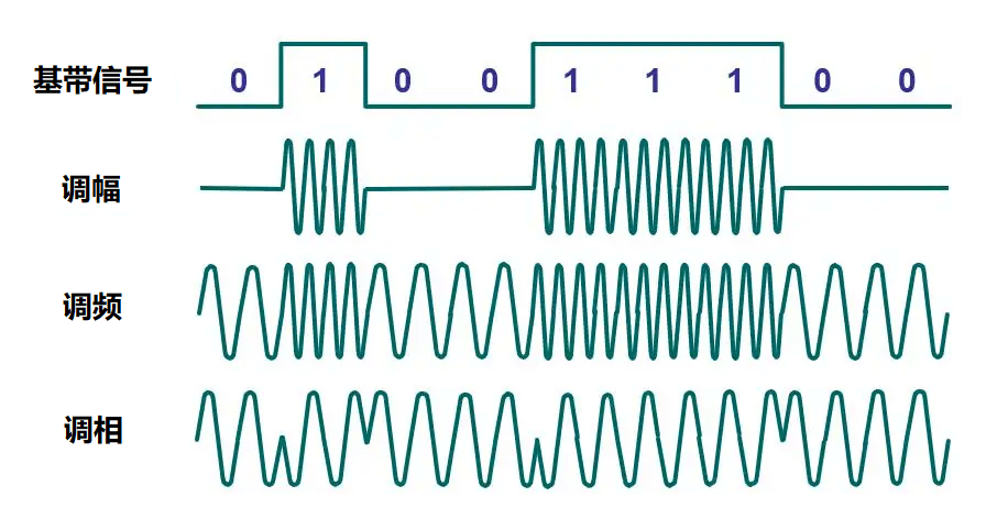
Similar to phase modulation, frequency modulation can also be divided into absolute frequency modulation and relative frequency modulation. Absolute frequency modulation directly maps information onto the frequency of the optical signal, while relative frequency modulation represents information by changing the frequency offset of the optical signal. The advantage of frequency modulation is its wide bandwidth utilization and good resistance to attenuation, making it suitable for long-distance, high-speed optical communication systems. In submarine cable communication systems, frequency modulation is used to achieve high-capacity data transmission, often combined with wavelength division multiplexing (WDM) technology to transmit multiple optical signals of different frequencies simultaneously through a single fiber, significantly increasing the communication capacity.
2.1.4 Polarization Modulation
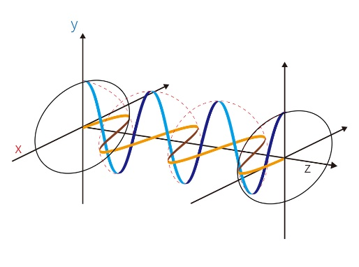
Polarization modulation carries information by changing the polarization state of the optical signal. Light waves are transverse waves, with their vibration direction perpendicular to the direction of propagation, and the polarization state describes the orientation of the vibration direction in space. Common polarization states include linear polarization, circular polarization, and elliptical polarization. The advantage of polarization modulation is that it fully utilizes the polarization characteristics of optical fibers, improving communication capacity and transmission efficiency. In advanced optical communication systems, polarization multiplexing technology allows the simultaneous transmission of two orthogonally polarized optical signals through a single fiber, effectively doubling the data transmission rate. In high-speed optical communication systems exceeding 100 Gbps, polarization multiplexing has become a key technology for achieving high-capacity transmission.
2.2 Optical Signal Transmission
The core of fiber optic communication is the transmission of optical signals through optical fibers. As mentioned earlier, the transmission of optical signals in fibers is based on total internal reflection. This phenomenon allows optical signals to travel long distances without significant attenuation, unlike traditional cables where electromagnetic wave leakage causes rapid signal degradation. The transmission of optical signals is a complex physical process, influenced by factors such as the wavelength or mode of the optical signal, the structure and material of the fiber, leading to effects like dispersion and loss.
2.2.1 Types of Optical Fibers
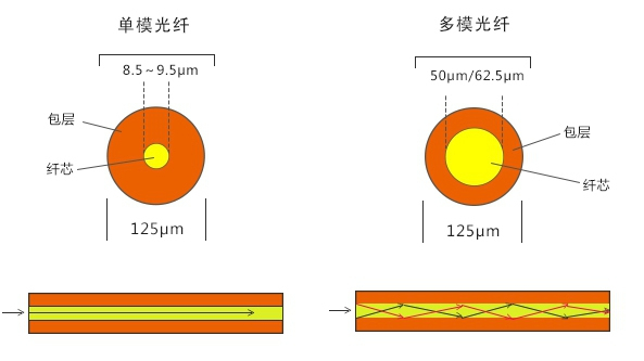
Optical fibers are mainly divided into two types: single-mode fibers and multi-mode fibers. Single-mode fibers have a small core diameter and can only transmit one mode of optical signal. Due to their low loss and low dispersion, single-mode fibers offer high signal transmission quality and can achieve transmission distances of tens to hundreds of kilometers, making them suitable for long-distance, high-bandwidth communication. Multi-mode fibers have a larger core diameter and can transmit multiple modes of optical signals, but their higher loss and dispersion limit them to short-distance, medium-bandwidth communication, such as in local area networks (LANs).
2.2.2 Dispersion
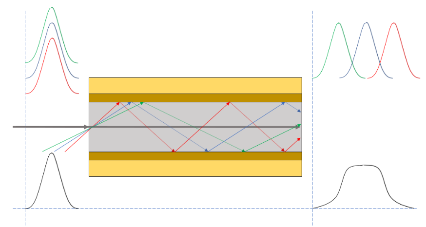
Dispersion refers to the distortion of optical signals during transmission in fibers due to different wavelengths or modes propagating at different speeds. The main types of dispersion include modal dispersion and chromatic dispersion. Modal dispersion occurs in multi-mode fibers, where different modes of optical signals travel at different speeds and path lengths, leading to signal distortion. Modal dispersion is a major factor affecting the quality of optical signal transmission, and single-mode fibers do not suffer from intermodal dispersion. Chromatic dispersion, on the other hand, occurs when different wavelengths of light travel at different speeds in the fiber, causing signal distortion. Dispersion limits the transmission distance and speed of optical signals, so in high-speed, long-distance optical communication systems, dispersion compensation techniques are employed to mitigate its effects. For example, dispersion-compensating fibers (DCF) and fiber Bragg gratings (FBG) are used to effectively compensate for dispersion, improving the quality of optical signal transmission.
2.2.3 Loss

Optical signals experience loss during transmission in fibers, primarily due to the following factors:
- Absorption Loss: The absorption of light by the fiber material itself, leading to a reduction in signal strength.
- Scattering Loss: Scattering of light due to inhomogeneities within the fiber, causing some of the light to scatter in other directions and reducing signal strength.
- Bending Loss: When the fiber is bent, some of the light leaks from the core into the cladding, causing signal loss. The smaller the bending radius, the greater the loss.
- Connection Loss: Losses at fiber connection points, such as splices or connectors, also contribute to signal degradation.
2.3 Optical Signal Demodulation
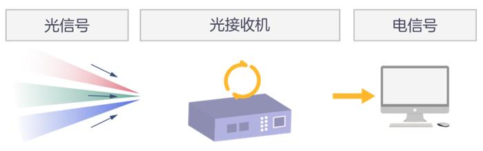
After the optical signal is transmitted through the fiber and reaches the receiving end, the information carried by the optical signal must be extracted. This process is known as optical signal demodulation. The demodulation method corresponds to the modulation method and includes intensity demodulation, phase demodulation, frequency demodulation, and polarization demodulation.
2.3.1 Intensity Demodulation

Intensity demodulation is used for intensity-modulated optical signals. At the receiving end, a photodetector converts the intensity variations of the optical signal into amplitude variations of an electrical signal, thereby extracting the information. Photodetectors are key components in intensity demodulation, with common types including photodiodes and photomultiplier tubes. Photodiodes offer high response speed and good linearity, making them suitable for high-speed, low-noise optical signal detection. Photomultiplier tubes, on the other hand, provide high sensitivity and gain, enabling effective detection of weak optical signals.
In marine optical cable communication systems, intensity demodulation is widely used in various digital and analog communication applications. For example, in shipboard video surveillance systems, intensity demodulation can restore video image information from the optical signal, enabling real-time monitoring of the ship’s internal and external environments.
2.3.2 Phase Demodulation
Phase demodulation is used for phase-modulated optical signals. A phase detector converts the phase variations of the optical signal into variations in an electrical signal, thereby extracting the original information. Phase detectors can be implemented in various ways, such as heterodyne detection, homodyne detection, and phase-shift keying (PSK) demodulation. Heterodyne detection uses a local oscillator to generate a reference optical signal, which is mixed with the received optical signal to produce an intermediate frequency signal. The phase of this intermediate frequency signal is related to the phase of the original optical signal, and detecting its phase variations enables phase demodulation. Homodyne detection, on the other hand, directly interferes the reference optical signal with the received optical signal to produce a DC signal, whose amplitude is related to the phase of the optical signal. Detecting the amplitude variations of this DC signal enables phase demodulation. PSK demodulation divides the phase-modulated optical signal into multiple phase states, each corresponding to a specific information symbol. By detecting the phase state of the optical signal, the information can be demodulated.
In shipboard navigation systems, phase demodulation is used to process phase-modulated optical signals from fiber optic gyroscopes, enabling precise measurement of the ship’s angular velocity and attitude, which is crucial for navigation and positioning.
2.3.3 Frequency Demodulation
Frequency demodulation is used for frequency-modulated optical signals. At the receiving end, a frequency detector converts the frequency variations of the optical signal into variations in an electrical signal, thereby extracting the original information. Frequency detectors can be implemented using direct detection or phase-locked loop (PLL) detection. Direct detection relies on the frequency variations of the optical signal causing changes in the output current of the photodetector, enabling frequency demodulation. PLL detection uses a phase-locked loop circuit to lock the frequency of the received optical signal to that of a local oscillator. By detecting the output signal of the PLL, frequency demodulation can be achieved.
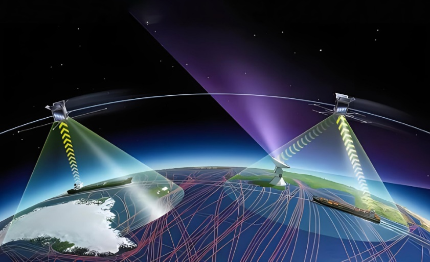
Frequency demodulation is widely used in shipboard communication systems. For example, in satellite communication systems, frequency demodulation can restore original data information from frequency-modulated optical signals transmitted by satellites, enabling high-speed data transmission between the ship and the satellite.
2.3.4 Polarization Demodulation
Polarization demodulation is used for polarization-modulated optical signals. A polarization detector converts the polarization state variations of the optical signal into variations in an electrical signal, thereby extracting the original information. Polarization detectors can be implemented using polarization beam splitters or polarization controllers. A polarization beam splitter separates optical signals of different polarization states, and by detecting the intensity or phase variations of these signals, polarization demodulation can be achieved. A polarization controller adjusts and controls the polarization state of the optical signal to match the polarization detector at the receiving end, enabling effective polarization demodulation. In high-speed shipboard optical communication systems, polarization demodulation is used to process polarization-multiplexed optical signals, effectively doubling the data transmission rate and improving the ship’s communication capacity and efficiency.
3. Summary
Through optical signal modulation, fiber transmission, and optical signal demodulation, we achieve the conversion of electrical signals to optical signals, the transmission of optical signals, and the conversion of optical signals back to electrical signals. Different modulation methods have corresponding demodulation methods, each suitable for processing different types of information, while the transmission of optical signals occurs entirely within the optical fibers inside the cable. Marine optical cables ensure efficient, stable, and reliable information transmission, making them widely used in the shipping and offshore industries.
The above is an introduction to the working principles of marine optical cables. We hope this article helps you understand how marine optical cables work.
Post time: Feb-24-2025